Introduction
In this article I'll run you through the steps of ramping up the voltage on your X800 (Pro/Pro VIVO/XT/XT PE). As always, the familar warning of "This will void the warranty" and "We take no responsibility of any kind should you damage your video card" applies before we start. Remember to take your time and don't over do it. You should seriously consider replacing the stock HSF if you plan to crank high on the overclock . Check out our GPU Heat Sink Fan Reviews here. Also, should you have any questions or information you wish to share, please post them here.Before you Begin
I'd like to make clear a important side note before you begin. In regards to "How hot is too hot?", I see and receive this question a lot. First I want to post ATI's official X800 GPU temp specs.Some interesting numbers to say the least. Having posted the info which should provide you with a base to which to compare your temps too, ie 80°C and even 90°C is still within specs. But having said that I'd like to share some words of wisdom from one named ViperJohn
Thermal Parameter Value temperature Maximum recommended ASIC case (or center of die backside for flip chip) 105°C Absolute maximum rated junction temperature: TJmax 125°C Minimum ambient operating temperature 0°C
So before you put the juice to that piece of hardware keep those words in the back of your mind.
ATI says 95°C is okay but it may not run clean either. I had an ASUS XT-PE that ran at 80C stone stock in the 3DM01se Nature torture loop. While they say it is okay there is a catch to running hot.
For every 10°C you increase a discrete parts (memory chips, cores, Mosfets, IC's, etc) average operating temperature you cut its lifespan in 1/2 what ever that given lifespan may be. Conversely for every 10°C you lower the average operating temperature you double the parts lifespan. It doesn't take a rocket scientist to conclude that a card that runs 60C will have an average life span that is 4 times longer than if the same card runs 80°C.
The above is the reason that a properly modded card can have a longer lifespan that the same card will stock.
John
Max. safe voltages
| VGPU | |
|---|---|
| Stock: | 1.31V - 1.41V |
| Air cooling: | ~1.45V |
| Water cooling: | ~1.7V |
| Phase change: | ~1.85V |
| VDD | |
|---|---|
| Stock: | 1.95V - 2.05V |
| Active + Passive cooling: | 2.45V |
| VDDQ | |
|---|---|
| Stock: | 2.04V - 2.10V |
Since most people prefer the pencil method, I'll start with that vmod first and come back to the resistor vmod.
Pencil Mods
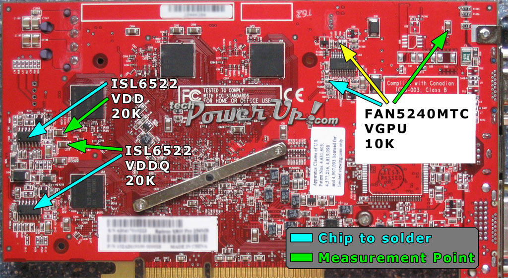
Image 1

Image 2

Image 3
Tools and Supplies
- Digital Multimeter (a must have to complete mod safely)
- Electrical Tape (get the color that matches your PCB)
- 2b Pencil (works the best, found one at Staples in Drafting Department)
Getting Started
Before we get down to work, lets run through the multimeter to make sure we're on the same page. You'll be using two different settings. One to check the voltage before and after we make our changes. The second to check the resistance in Ohms of the resistors we're using our 2b pencil on to safely lower their resistance to raise the voltage. To check the voltage for the VCore and VMem starting measurements set the multimeter to DCV 20v and to check Ohm resistance you'll set the meter to Ohms 2k or 20k depending on the resistor we're working with.I'd like to note that you don't need to do all of the next steps if you're not doing all of the vmods. Try the VCore vmod first then move on to the next one if you feel you need to.
So grab a pencil and paper (should already have a pencil) we're going to write down our starting voltages. Starting with Image 1 locate the green arrow pointing to the capacitor in the top right hand corner labeled C60. Now with the system running and the side cover off visually inspect the area to first locate the capacitor and making sure there isn't anything in the way. Set your meter to DCV 20 V before placing the black lead of your meter on the screw holding in the video card, this is ground. Important when touching card with a meter lead that you don't accidently ground something out. Carefully place the red lead on the top side of capacitor C60 (you're upsidedown from the pic facing the card). Your meter should be reading around 1.39v, cards vary from manufacture to manufacture. Write that VCore number down for future reference. There is not a measure point for the IGPU Vmod that I'm aware of at this time.
For the time being lets move on to the VDD (VMem) measure point. Again in Image 1 locate the green arrow pointing to our measure point, over to the left of the card labeled C213. A closer view in Image 3, it's the top capacitor in the top right hand corner. With the same steps we used in the previous measure point. Place the black lead on ground carefully placing the red lead on left side of C213 (you're upsidedown from the pic facing the card). Your meter should be reading around 2.00v. Write that VMem number down for future reference.
Next measurement we'll check before we start the mod will be VDDQ. Find the measure point in Image 1, green arrow pointing to capacitor C215. Right below the VDD capacitor, closer view in Image 3. Once more with the same steps as before place the black lead on ground carefully placing the red lead on the left side of C215 (you're upsidedown from the pic facing the card). Your meter should be reading around 2.08v. Write your VDDQ number down for, you guessed it, future reference.
Pencil Time
Time to shut down the system and take out the card, your work area should be static free. Yes, at this point you should be reading from a printed document. Basically what we are trying to do is use our 2b pencil to reduce resistance on the selected resistor. You'll need to measure the resistance in Ohms first, by placing the black lead on one side and the red lead on the other side of the resistor, write it down it's our starting Ohm reading. Then gently run your pencil along the side of the resistor from one end to the other. Do a couple swipes then check again with the meter. Using the number you've written down subtract the new reading. For example if your starting Ohm reading is .418k and your new ohm reading is .400k obviously it's a 18k ohm drop in resistance. If you go by the rule of 15k Ohms equals roughly .04 V to .06 Volts. Add the .04 V - .06 V to the reading that you saved for future reference, for example the VCore reading of 1.39 V your voltage should now be around 1.43 V - 1.45 V. A 10k variable resistor will give you around .04 Volts so again that's around 15 Ohms you need to reduce your resistor.Keep in mind that if you want your card to last awhile don't get greedy.
VCore Vmod
Using Image 2 as our guide locate the the resistor R1597 that is under the pencil labeled VGPU. This is the resistor you will use the 2b pencil on following the steps we went through above. Set your multimeter to 20k Ohms. A VCore voltage of 1.45v to 1.50v should work well. After you have reduced the resistance place the card back in and power up. Check your VCore voltage again to verify the amount of voltage you're now running at. Test the card for artifacts and lockups. If all is well, use a piece of electrical tape and cover the resistor you modded. Review the max voltages we suggested for cooling needs.GPU Over Current Protection Vmod
This mod is only needed if you are applying a high VCore vmod. This mod raises the limit that you can obtain with the VCore vmod. In Image 2we use a 20k Ohm reduction in resistance for OCP vmod, which is applied to resistor R1596. Since there isn't a measure point, remove the card and set your meter to 200k. Check the resistance on the resistor R1596 which should be around 40k Ohms. As \\mAr did lower the resistance by 20k Ohms. This one is in a tight spot so you may want to try to pencil the top of the resistor to make it easier.VDD (VMem) Vmod
In Image 3 locate the VDD labeled pencil above the resistor R311. This is the resistor you will use the 2b pencil on following the steps we went through above. Set your multimeter to 20k Ohms. A 20k variable resistor which will give you around .08v Volts, you'll need to reduce the resistance around 30 Ohms. A VMem voltage of 2.08 V to 2.12 V will work fine. After you reduce the resistance place the card back in and power up. Check your VMem voltage to verify the amount of voltage you're running your memory at. As we did in the VCore vmod, test the card for artifacts and lockups. If you're loving life, tape that bad boy up.VDDQ Vmod
This one will be a little tough given the resistor is in a tight spot. Looking at Image 3 the pencil labeled VDDQ above resistor R256, this is the one you'll need to pencil mod to increase VDDQ voltage. Set your meter to 2k Ohms this time. With the info of a 20k variable resistor giving .08 Volts we'll need to reduce resistance around 30 Ohms. A VDDQ voltage of 2.16 V to 2.18 V will help with both VCore and VMem. Check the voltage to verify the amount of voltage you're running at. Test for artifacts and lockups. Use the tape to keep the graphite in place.My 2 Cents
Before I go into using soldered VR vmods I wanted to finish the pencil vmod section with my 2 cents worth. I tried to write the pencil vmod with newbies or first time modders in mind. The pencil mod can be applied easily and be effective if you take your time. Don't get caught up in seeing someone else's speed and think you can do it too. Not all cards oc the same and along with cooling methods can determine your final outcome. The forums here at techPowerUp! are filled with people who will not hesitate to help by answering a question. Even still if it all seems like too much you can always send your video card to ViperJohn who does quality voltmodding work.Using Variable Resistors
This section I decided will be brief due to time restraints and less descriptive. Understanding the same warnings as posted previously in the begining of the article. You should read the "Introduction" and "Before you Begin" sections.There are several VR How-Tos on the web. Each one has a different tweak, it's one of those more than one way to skin a cat deals. But we'll just do the basic VR to resistor solder.
Image 4

Image 5

Image 6
Tools and Supplies
To do these mods you should aready have soldering skills and should be using a low wattage iron. I also assumed that you would be using a magnifying glass and until now didn't think to mention it.- Digital Multimeter (have to have one)
- Glue Gun (to set VR in place)
- Variable Resistors: 1x 10k Ohm, 1x 250k Ohm, 2x 20k Ohm
Next read the "Getting Started" section to get your default voltage. This can be important to get an idea of where your voltage will be when you crank up the card. You can still use the same table as the pencil mod. What I mean by that is if the default Ohm reading of the VGPU is at 420 and you add the 10k VR, then given that a 10k VR will give you around .04v which in turn equals 15 Ohms then after adding the VR your new Ohm reading should be around 405 Ohms.
VR VGPU
Locating the resistor R1597 in Image 5 you will use the 10k VR. Set the VR to 10k or as close to 10k as it will go using your mulitimeter. Check the resistance on R1597 to compare after you solder the VR. You can either solder the VR to the resistor directly or you can use wires. After soldering the VR on check the resistance. Remember a 10k VR should give you around 15 Ohms. Test your card and verify the voltage.VR IGPU Over Current Protection Vmod
Locate resistor R1596 in Image 5 and set your VR to 250k. Check the resistance on the resistor to compare after you solder the VR on. Again after soldering the VR on check the resistance. Like with the pencil mod you want to drop the resistence around 20k Ohms.VR VDD (VMem) Vmod
Using Image 6 we will solder a 20k VR to the pins 5 & 7 of the VDD chip. Set the resistor to 20k and check the resistance before then after. Test your card and verify the voltage.VR VDDQ Vmod
Same as the VDD vmod but on a different ISL6522CB chip below the VDD locate the VDDQ in Image 6. Just like the VDD set the VR to 20k and check the resistance before then after. Test your card and verify the voltage.Conclusion
Remember to check and recheck before you place the card in and turn it on. By checking the resistence before and after can help deterrmine if you've made a mistake. Some may have you vmod and then test by placing the card in and powering it up. You don't drive blind, so don't mod blind.Unlike the Pencil Vmod using the VR takes good soldering skills. I can contest to that and even though my soldering is rusty I still managed to do a few until I had slipped on my own card. Needless to say accidents do happen. So please take your time and be careful. But above all be safe.
0 comment on "Radeon X800 Pro/XT/XT PE Voltmods"
Post a Comment