Introduction
When DFI released the LANPARTY UT nF3 250Gb board, all overclockers had it on their, "must have" list. The board had more tweaking options than any other board available for the Athlon64 CPUs.But there was one thing that was a bit sad:
Soon after its release, some eager BIOS modders discovered that the board had hidden options in BIOS for up to 4V VDimm (unofficial modded BIOS versions are available). First this seemed to be very good news, but unfortunately DFI had decided to generate VDimm using the 3.3V-rail, thus max. useable VDimm was still 3.1-3.2V (like in the official BIOS versions). One way to get higher VDimm was increasing the 3.3V-rail of your Power-Supply, but that led to new problems in some cases. With the modded 3.3V-rail, users complained about cold boot problems (the reason for that "bug" is that the board always uses 2.5V VDimm for the first start on a cold boot, instead of using the value set in BIOS) and a max. VDimm of ~3.5V regardless of how high they had set their PSU's 3.3V-rail (any VDimm higher than ~3.5V led to no boot at all).
Now that is where my mod comes into play. As I already said, the problems with high VDimm were mainly caused by the increased 3.3V rail. My solution to this is simply using the 5V-rail instead. To make this possible you need to do major modifications to your motherboard, and your warranty will be void for sure, but if you are a real enthusiast, this won't bother you at all anyway.
Required parts
Here are the parts that you will need for this modification:- a good soldering iron (Ersa 25W in my case)
- rosin core solder and solder flux (for example "colophony")
- some cables (I used 1.5mm diameter cabling, made from copper strands, normally used for hi-fi systems)
- some heatshrink-tubing and hotglue
- and perhaps some isolating protection lacquer
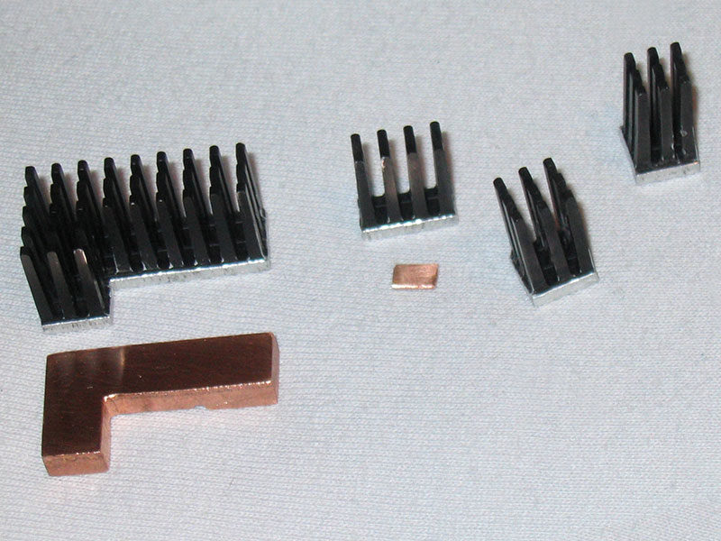
- heatsinks and thermal epoxy (an alternative to the thermal epoxy would be to buy 5-minute two component epoxy and then mix that with thermal compound; I often used that method and it always worked fine)
- either one 100K (trimmer-) potentiometer or two 50K (trimmer-) potentiometers for the hardware VDimm-Mod
Afterwards, adjust the potentiometer(s) to the maximum resistance. Those are the values to start with - they are very important!
5V as VDimm-source Mod
Datasheet of the MOSFET: http://www.samhop.com.tw/pdf/SD(DU)9916.pdf
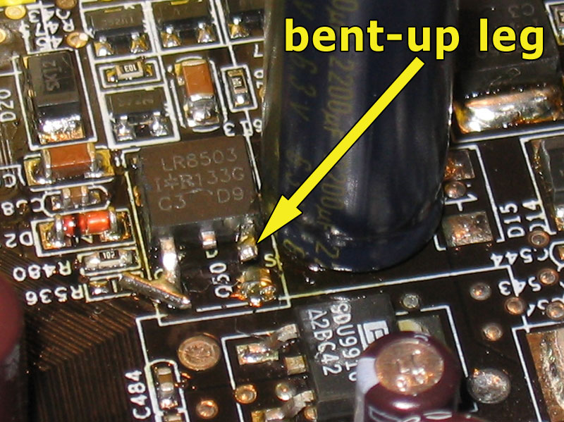
The mod is quite simple in theory. You have to bend up the MOSFET's source pin to disconnect it from the motherboard and then solder a 5V wire to it. This MOSFET is Q50 which is located directly under the DIMM slots. Don't wonder why your MOSFET looks different than the one in my pictures, I had to replace mine, so don't worry. The source pin is even marked with an "S" on the PCB. A good way to get 5V is from the 5V pin of the ATX power connector.
While this sounds easy, unfortunately it is a bit harder in practice. The problem is that it's nearly impossible to just remove the MOSFET's source-pin from the solder pad on the board, without damaging the MOSFET or breaking the pin.
The solution to this problem is to remove the whole MOSFET, bend up the source-pin and then solder it in again. After that, you are ready to finish the mod.
What you have to do then, is get a thick wire (there will be quite some amps going through it, when running good RAM at high volts and high clocks, that's why a thin wire won't be enough) and locate the 5V contacts on the backside of the board, where the ATX connector of your power supply gets connected to your board. Now you can just solder one end of the cable to the two 5V contacts and the other end to the bent up source-pin (MOSFET "Q50"). Make sure that the pin is bent up high enough, so there is no contact to the old solder-pad (which is connected to the 3.3V-line via the motherboard) when the cable is soldered in.
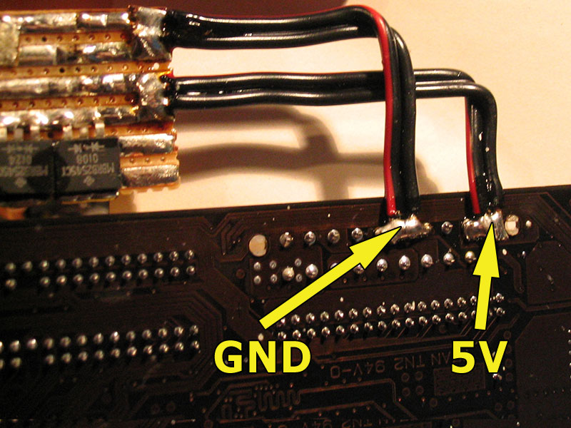
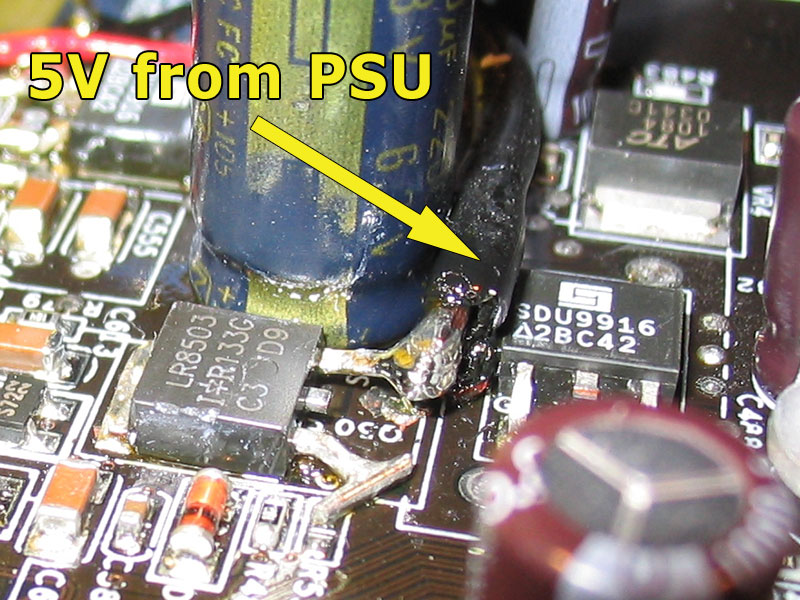
Optionally you can do it like I did and put in a capacitor (the ground connection in the picture is needed for the capacitor only. I used a 1000µF 6.3V low ESR cap). The capacitor filters the voltage a bit.
Another optional tweak is to add some


One rather bad side effect of this mod though, is that the MOSFET "Q38" gets hotter than before (hotter than with the standard 3.3V based VDimm supply; the MOSFETs are rated for up to 150°C, but that's only the MOSFETs; the surrounding components wouldn't like the hot climate :) ). I advise you not to run the modded board without additional cooling for at least this one MOSFET ("Q38"). In fact it would be best if you put heatsinks on the MOSFETS "Q50" and "Q38", in order to play it safe.

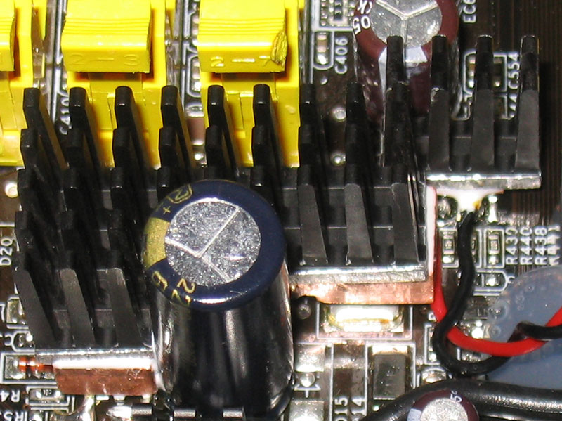
I had some problems while trying to figure out the perfect way to do this mod. I removed and soldered in MOSFETS and capacitors several times and after some successful tries, the MOSFETs' solder pads suddenly came off the board, i.e. they were broken. Lucky as I am, I had tested all the solder pads for connections before and knew what they were connected to. That's why you see more connections than just the cable connected to the MOSFET's source-pin. In the process of finishing the mod, I had to fix all MOSFET solder pads, as they were all broken. Here are all the fixes, in case you should damage one of your solder pads, too:


Additional hardware Vdimm-Mod
Datasheet of the chip: http://www.semiconductors.philips.com/acrobat/datasheets/LMX58_A_2904_XX532_4.pdf
I already mentioned that there are unofficial, unsupported BIOS versions that feature up to 4V VDimm. Now you'll perhaps ask, "why should I do the hardware VDimm-Mod then?". The answer is simple. As I explained above the board has cold boot problems when running high Vdimm.
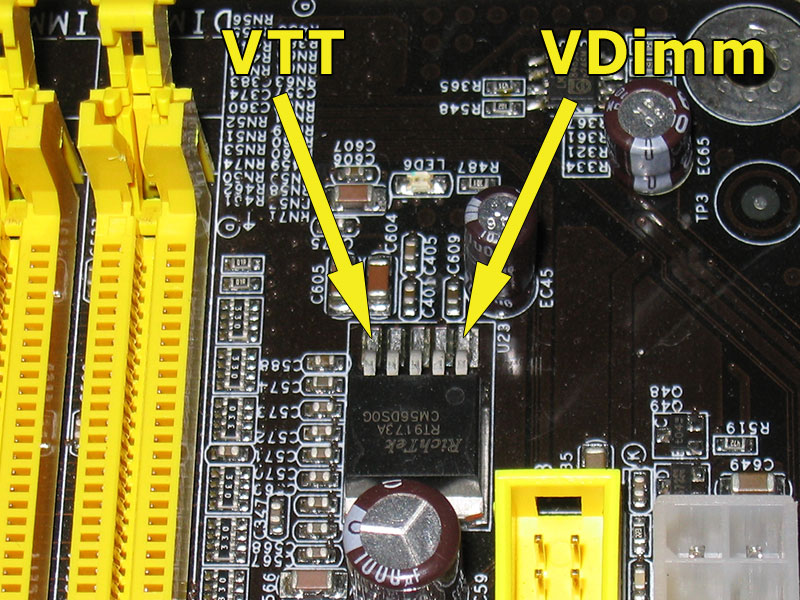
The only way to fix this, is doing this easy hardware mod, that makes the board start with the VDimm that you adjusted via potentiometer, even on the first boot. It let's you adjust the VDimm to your liking and most important with much more precision (BIOS only let's you choose VDimm in steps of 0.1V, while you can adjust it in steps of at least 0.01V with the help of the hardware mod). For this mod you can either use a single 100K potentiometer (precision ~6.67K per full turn), or if you wish to have a little more precision, 2x 50K potentiometers (precision ~3.33K per full turn), connected in series, which again gives you a final resistance of 100K. Both ways will work, but it's up to you, to decide which one you like more. :)

The 100K potentiometer(s) need(s) to be soldered in between pin#3 and pin#8 of the LM358 chip („U28"). Locate the pins according to the datasheet, or just have a look at my pictures and then connect the outer pin of the potentiometer(s) to pin#3 and the middle potentiometer-pin to pin#8 on the LM358 chip. Remember to have the potentiometer(s) set to maximum resistance before powering up your board.
Update:
Had to work on the board again today, as it had started to freak out after another additional mod. While fixing this issue I tried something that I had wanted to try from the beginning. I found out that using Pin#2 and Pin#4(Ground) for the Vdimm-Mod also works great. So you can choose between both methods. Either you use the poti between Pin#3 and #8, or you can also use Pin#2 and #4. The combination #2 and #4 is a little better IMHO, because its accessability is simply better. But in the end, the outcome is the same.

In case you might be irritated because you see three potentiometers connected in series on my pics, don't worry, it'll work perfectly with one or two. I only used three first and then just kept it that way, although two would have been enough.
I did the following additional/optional modifications to my board:
- new chipset heatsink, custom made from an Alpha PAL153U 1U CPU cooler
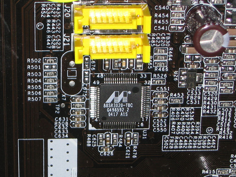
- additional heatsinks for several other chips (VCore-MOSFETs, Marvell PHY chip 88SR3020-TBC, ICS93742AF clock buffer etc.; especially the latter two do indeed get quite hot)
- redid solder-joints for all the capacitors that belong to the VCore- and VDimm-circuits, because they were not perfectly soldered in


Warning:
All modifications are done at your own risk! I am not responsible for any damage caused by the modifications described above! Any hardware modification will definitely void your warranty! Keep that in mind.
0 comment on "DFI LanParty NF3 VDimm Mod"
Post a Comment