- one 50K (trimmer-) potentiometer for the VCore-Mod
- one 20K (trimmer-) potentiometer for the VDD-Mod
- one 5K (trimmer-) Potentiometer for the VDimm-Mod
- a good soldering iron (Ersa 25W in my case)
- rosin core solder and a resin (for example „colophony")
- some heatshrink tubing and hotglue
- and perhaps some isolating protection lacquer
Afterwards, adjust all potentiometers to the maximum resistance, because that's the value to start with - this is very important!
VCore-Mod
Datasheet of the chip:http://www.richtek-ic.com.tw/Product/Docs/DS9241AB-02%283%29.pdf
Connect the outer pin of the 50K potentiometer to Pin #14 (Vsen) of the RT9241B chip and then connect the middle contact of the potentiomter to Ground.
Pin #13 of the RT9241B is a ground pin, but I felt that it was too cramped for me to solder the two cables next to each other. I used a thicker cable than I normally would, because I had read that it would give more stable VCore values in comparison to using a thinner wire (reference to Hell-Fire's postings on XtremeSystems). In order to ground the middle pin of the poti, I just put the cable through a hole in the PCB, just next to the P4-connector on the motherboard. On the backside of the mainboard, I connected the cable to one of the two ground pins of the P4-connector.


VDD-Mod
Datasheet of the chip:http://www.richtek-ic.com.tw/Product/Docs/DS9203A-06P%281%29.pdf
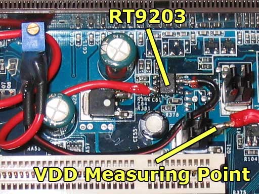
Connect the outer pin of the 20K potentiometer to Pin #8 (FB) of the RT9203 chip. Then connect the potentiometer's middle contact to Pin #3 (Ground/GND) on RT9203.
Measuring point for VDD is the right leg of the mosfet directly under (righthand) the RT9203 chip.
VDimm-Mod
Datasheet of the chip:http://www.national.com/JPN/ds/LM/LM431.pdf
The outer pin of the 5K potentiometer needs to be connected to LM431's Pin #8 (Reference). After that you have to connect the middle pin of the potentiomter to ground. Since the LM431 chip does not have a Ground/GND-Pin (NC is NOT Ground), you willl have to think about something different. I used a longer, thicker wire again and put this wire through the second hole in the PCB, next to the P4-connector (routed the wire along the backside of the AGP-port). Then, like with the VCore-Mod, just connect the wire to the second ground point of the P4 Connector.
Measuring point for Vdimm is the left leg of the mosfet directly next (lefthand) to the first Dimm-slot (have a look at the pics).

Overview

That's all the info needed to do the mods!
P.S.: I did the following additional modifications to my board:
- Hardware-L12-Mod (used the How-To from http://www.ocinside.de/html/workshop/pinmod/amd_pinmod_d.html).
- additional cabling to connect a second PSU
- Northbridge and Southbridge were lapped and I put heatsinks on all those chips that I thought would benefit from it


Warning:
All modifications are done at your own risk! I am not responsible for any damage caused by the mods!
0 comment on "Shuttle AN35N-Ultra Voltmods"
Post a Comment